Objectives
This lab introduces hands-on experience about tuning a orientational PID controller to control a car's yaw to be maintained to the setpoint (which may change while running), utilizing data sent via BLE for debugging.
Prelab
Code on the Stunt Car: The orientational PID controller is wrapped in the function "PID_ROT()". Once the orientational PID controller is enabled, it will try to maintain the orientation to the setpoint and store Yaw data accumulated from the Gyroscope for 10 seconds. When reaching the time limit, the PID controller will shutdown itself and apply the break to stop the car. After that, function sendIMU() will be called to send the collected data
(including time stamps, Yaw angles, motor PWM counts, desired Yaw setpoints) via BLE. When exiting the orientational PID controller, parameters will be reset so that experiments can be conducted without rebooting the board.
                                        void loop() {

                                            // only move when ble connected.
                                            BLEDevice central = BLE.central();
                                            if(central){

                                              digitalWrite(LED_BUILTIN, HIGH);
                                              Serial.print("Connected to: ");
                                              Serial.println(central.address());

                                              while(central.connected()){
                                                read_data(); // get the robot command and related messages from BLE

                                                // wheel control and PID based on ToF sensors
                                                // ---- check ToF data ----
                                                tofUpdate();
                                                if(printDebug){
                                                  printDS();
                                                }

                                                // ---- PID to refresh the speedL and speedR according to ToF readings
                                                PID_FB();

                                                // ---- PID to control the rotation (yaw)
                                                PID_ROT();

                                                // ---- wheel control ----
                                                wheelCtrl1(speedL, speedR);

                                                // ---- send data over BLE
                                                if(startSend){
                                                  sendToF();
                                                }

                                                if(startSendIMU){
                                                  sendIMU();
                                                }

                                              }

                                              // if not connected to central
                                              digitalWrite(LED_BUILTIN, LOW);
                                              wheelBrkCtrl(100);  // will clear the speedL and speedR.
                                              delay(10);

                                            }

                                          }
Code on PC: As usual, after PC is connected to the car via BLE, we set the P/I/D parameters and the desired distance from object using "ble.send_command()". Then, we enable the notification handler and trigger orientational PID controller using command. After that, we wait for 5 seconds and then turn off the notification handler. About 360 groups of data points are stored as a global variable after this process.
To change the setpoint during the orientational PID controller is running, we use the following code to first set the Yaw to 0 and start controller, then set Yaw to 90 after waiting for 5 seconds.
                                        ble.start_notify(ble.uuid['RX_STRING'], rx_handler_IMU)
                                        ble.send_command(CMD.SET_TARGET_YAW, "0")
                                        ble.send_command(CMD.PID_ROT_ON, "")
                                        time.sleep(5)  # wait for 5 secs.
                                        ble.send_command(CMD.SET_TARGET_YAW, "90")
                                        ble.send_command(CMD.SET_I_ROT, "0")
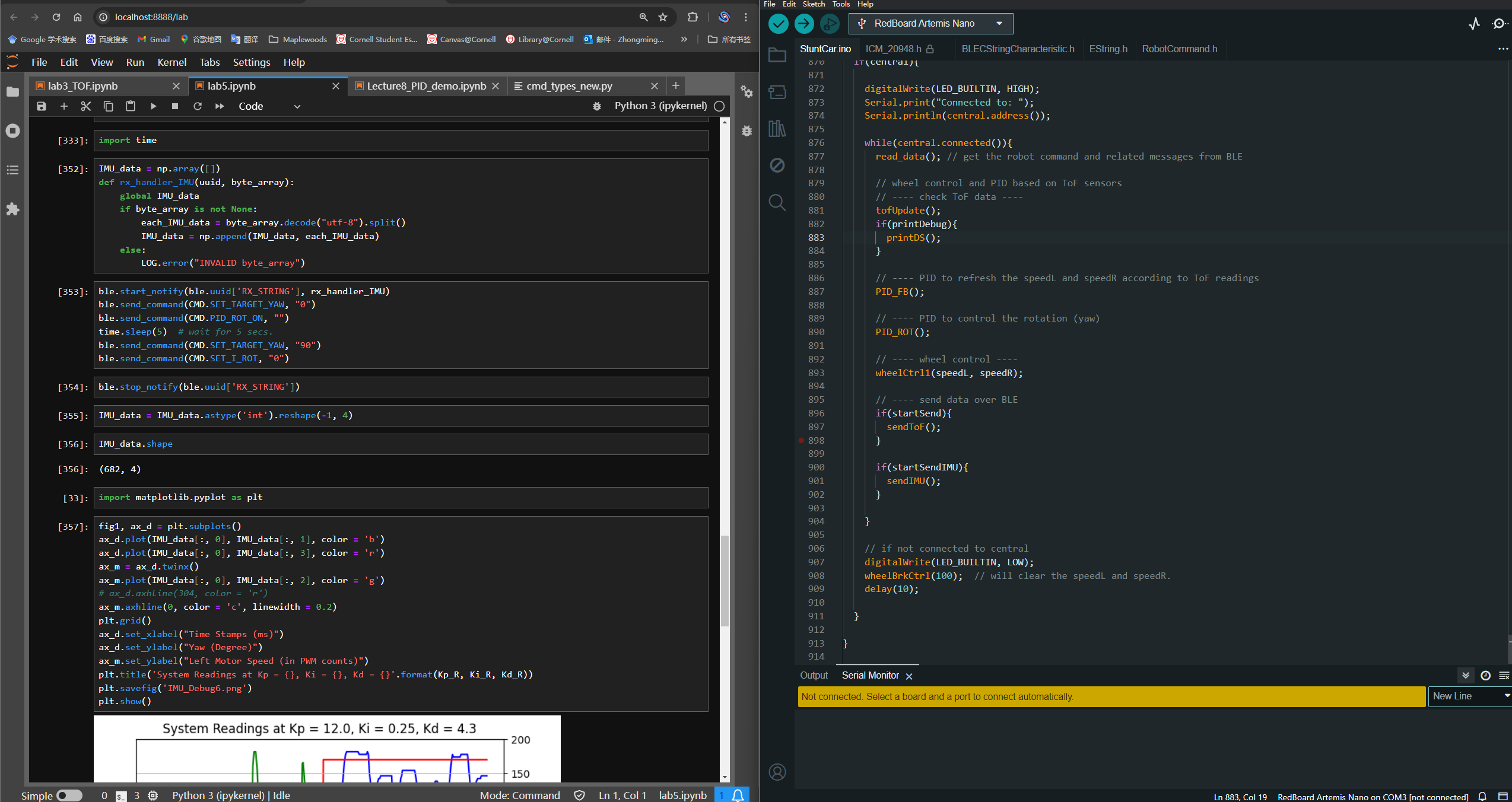
Check out the screenshot below to see the implementation.
Additional Module: IMU calibration. Since the Gyroscope drifts rapidly as integration continues, we should substract a fixed bias to counter the drifts. This can be implemented on the board by placing the car still and measure the Yaw drift after a fixed duration (20 seconds in my code). The bias can be calculated by \( bias = \frac{drift}{duration} \). The drift in unit time is around \( 1.2\sim1.3 \) deg/sec. The following function can be called via BLE command. After running this function, the global bias variable will be updated.
                                        void yawCalibrate(){
                                            float time = micros(), time_p = micros(), dt = 0.0;
                                            float yaw = 0.0;
                                            Serial.println("Calibrating yaw drifting, place car still for 15 seconds.");
                                            while(1){
                                              if(micros() - time > 20000000.0){
                                                break;
                                              }
                                              dt = (micros() - time_p) / 1000000.0;
                                              time_p = micros();
                                              if(myICM.dataReady()){
                                                myICM.getAGMT();
                                                /* Computation variables */
                                                yaw = yaw + dt * myICM.gyrZ();  // should be compensated to counter drifting
                                              }
                                            }
                                            driftYaw = yaw / ((time_p - time) / 1000000.0);
                                            Serial.print("driftYaw is: ");
                                            Serial.println(driftYaw);
                                            // Serial.println(yaw);
                                          }
Task 1: P/I/D Discussion
As a feedback controller, the Proportional-Integral-Derivative controller (PID controller) takes the error between desired control goal and the actual status as the input. The math expression
is listed below.
\(
u(t) = K_p e(t) + K_i \int_{0}^t e(\tau) d\tau + K_d \frac{d e(t)}{d t}
\)
This mermaid flowchart may help explain the data stream of a PID controller:
In the orientational controller, error \( e(t) \) is the residue between the current Yaw and the setpoint; \( \int_0^t e(\tau) d\tau \) is the summation of errors in each loop; \( \frac{d e(t)}{dt} \) is the current error substracting by the previous error.
\( K_p \): Proportional parameter, to be multiplied with the residual between actual state and the desired setpoint. Increasing \( K_p \) helps accelerate the convergence speed, but with risk of adding overshoot. In the orientational PID controller, P can be relatively large to harvest faster response, but a excessive P value will cause the robot shaking continuously.
\( K_i \): Integrational parameter, to be multiplied with the integration (accumulated error over the timeline) of error. An appropriate value of \( K_i \) helps maintain the accuracy to the setpoint when the system converges. An excessively large \( K_i \) will introduce fluctuations to the system. An excessive I value will cause the robot spinning very fastly in place.
\( K_d \): Derivational parameter, to be multiplied with the derivation (or the residual between consecutive errors in the timeline) of error. Increasing \( K_d \) strengthens the system's stability and responsing speed to sudden changes to the state. An appropriate value of \( K_d \) helps suppress the overshoot of the system.
Task 2: Range / Sample Time Discussion
Range Discussion: the range of Gyroscope can be specified if we use the sparkfun ICM20948 Library. Since in this lab I am using the Pololu Library, the range of IMU seems not configurable. Instead of discussing the range,
it is worth mentioning that the Gyroscope will have a 1.2~1.3 deg/sec drift if we do not add any bias to the Z axis. Despite I have substracted a bias manually, the Pololu library indeed provides a built-in bias config API:
                                        //Gyro Bias
                                        ICM_20948_Status_e setBiasGyroX(int32_t newValue);
                                        ICM_20948_Status_e setBiasGyroY(int32_t newValue);
                                        ICM_20948_Status_e setBiasGyroZ(int32_t newValue);
                                        ICM_20948_Status_e getBiasGyroX(int32_t* bias);
                                        ICM_20948_Status_e getBiasGyroY(int32_t* bias);
                                        ICM_20948_Status_e getBiasGyroZ(int32_t* bias);
                                        //Accel Bias
                                        ICM_20948_Status_e setBiasAccelX(int32_t newValue);
                                        ICM_20948_Status_e setBiasAccelY(int32_t newValue);
                                        ICM_20948_Status_e setBiasAccelZ(int32_t newValue);
                                        ICM_20948_Status_e getBiasAccelX(int32_t* bias);
                                        ICM_20948_Status_e getBiasAccelY(int32_t* bias);
                                        ICM_20948_Status_e getBiasAccelZ(int32_t* bias);
                                        //CPass Bias
                                        ICM_20948_Status_e setBiasCPassX(int32_t newValue);
                                        ICM_20948_Status_e setBiasCPassY(int32_t newValue);
                                        ICM_20948_Status_e setBiasCPassZ(int32_t newValue);
                                        ICM_20948_Status_e getBiasCPassX(int32_t* bias);
                                        ICM_20948_Status_e getBiasCPassY(int32_t* bias);
                                        ICM_20948_Status_e getBiasCPassZ(int32_t* bias);
Sample Time Discussion: in average, the PC receives 340 data groups every 10 seconds, meaning that the main loop runs 34 times per second (34Hz). This is still much slower than the IMU hardware sampling rate (can be set to 100Hz for the Gyroscope).
Task 3: Demos of Reaching Task Goal
The code implementation of the orientational PID controller is shown below:
                                        void PID_ROT(){
                                            static float lastError = 0.0;
                                            static float lastTime = micros();
                                            float dt = (micros() - lastTime) / 1000000.0;
                                            lastTime = micros();
                                            static float yaw = 0.0; // degrees
                                            static float errorI = 0.0;
                                            static unsigned int idxStorage = 0, startTime = micros();
                                            // ---- update IMU reading ----
                                            if(PID_ROT_IS_ON){
                                              if(myICM.dataReady()){
                                                myICM.getAGMT();
                                                yaw = yaw + dt * myICM.gyrZ() - driftYaw * dt;  // substracted bias manually.
                                                // PID
                                                float errorD = 0.0;
                                                float error = desiredYaw - yaw;
                                                errorI = errorI + error * dt;
                                                errorD = error - lastError;
                                                lastError = error;
                                                Serial.print(yaw);
                                                Serial.print(" ");
                                                speedR = cutoffPWM(Kp_r * error + Ki_r * errorI + Kd_r * errorD);
                                                speedL = -speedR;
                                                Serial.print(speedL);
                                                Serial.print(" ");
                                                Serial.println(speedR);

                                                // store data into the arrays.
                                                if(startTime == 0){
                                                  startTime = micros();
                                                }
                                                if(micros() - startTime < maxDuration * 1000 && idxStorage < maxIMUAmount){ // store collected data while it's within time limit.
                                                  itoa(millis(), imuStamps[idxStorage], 10);
                                                  itoa(int(speedL), imuMotorSpeeds[idxStorage], 10);
                                                  itoa(int(yaw), imuStorage[idxStorage], 10);
                                                  itoa(int(desiredYaw), imuSetpoint[idxStorage], 10);
                                                  idxStorage += 1;
                                                }
                                                else{  // if the duration exceeds 10s or the data length exceeds the size of array, shut down the PID controller.
                                                  actualAmount = idxStorage;
                                                  PID_ROT_IS_ON = false;
                                                  wheelBrkCtrl(10);
                                                }
                                              }
                                            }
                                            else if(yaw != 0.0){  // if the PID should be shut down, reset the static vars here.
                                              yaw = 0.0;
                                              errorI = 0.0;
                                              speedL = 0.0;
                                              speedR = 0.0;
                                              lastError = 0.0;
                                              idxStorage = 0;
                                              startTime = 0;
                                              startSendIMU = true;
                                            }
                                          }
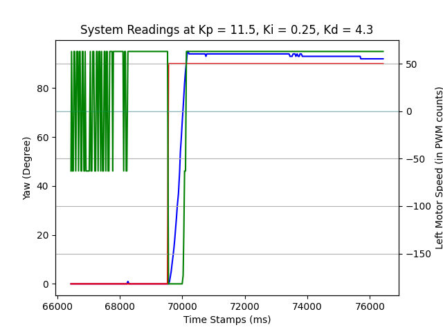
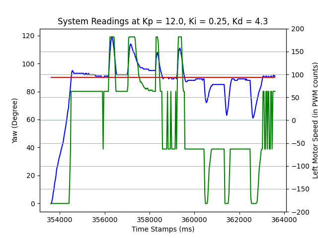
To tune the PID parameters, we start from small P/I values. Note: the battery of the car is running out when conducting this part, so the PID values may be a little bit large. Initially, I set \( K_p = 2.5, K_i = 0.1, K_d = 2.5 \), the car resists the external force at a very low speed. After increasing values, we can see a reasonable response speed as the following figure shows. The red line is the desired yaw setpoint, the green line represents the motor speed (PWM count), and the blue line symbols the actual Yaw in degrees. The setpoint is modified while the PID controller is running, no external force is applied in this round.
With the same params, place the car on the floor and kick the car gently with foot, we can see the following result.
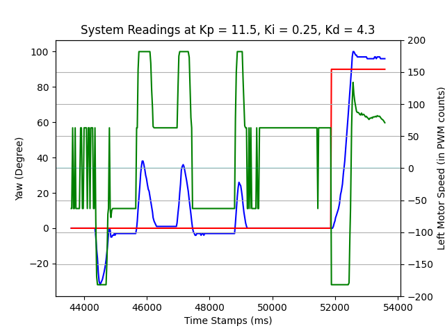
In the above debug diagram, we find that after timestamp 52000, the car converges slowly to the new setpoint, so a larger \( K_p \) is set in the next experiment:
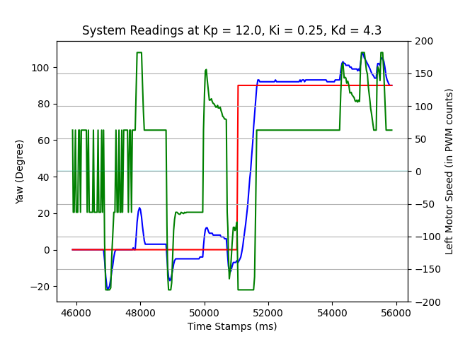
Now the car converges faster to the setpoints (both 0 and 90 degs) given even stronger external interference. As we can see in the above diagram, at time 54000 ~ 56000, the car returns to the setpoint after three consecutive kicks. It is also more robust when the setpoint is not changing:
There are several videos demonstrating the actual performance of the orientational PID controller, under kicks. (Note: the car is running out of battery so that the motors are weak. The car turns 90 degree after 5 seconds running the PID controller.)
(PS: the car is not responding to kicks in the last seconds because the PID controller shuts down itself after 10 secs.)
Additional Task: Wind-up Implementation and Discussion
Wind-up in the PID controller refers to the phenomenon when the integration error accumulates over time, it dominates over the all 3 error inputs and causes slow response and fluctuations to the system.
When the car approaches to the setpoint, the control output should slowly decrease (the motor speed should slowly decrease). But a large integrational term will make the sum of P/I/D terms still very large,
the decreasing rate of P/D terms is subtle compared with the increasing rate of the I term. Thus the motor will actually speed up instead of slowing down.
In the orientational PID controller, if the integrated error is exploding, the car will rotate at a very fast speed for a long time, and unlikely to stop and converge again. Thus we can cutoff the integrated error
within a maximum value of 10 degrees.
                                        float maxErrorI = 10.0;  // in degrees.
                                        float cutoffErrorI(float ErrorI){
                                            if(ErrorI > maxErrorI){
                                                ErrorI = maxErrorI;
                                            }
                                            return ErrorI;
                                        }
THE END