Objectives
This lab introduces hands-on experience about tuning a linear PID controller to control a car's distance from an object, utilizing data sent via BLE for debugging.
Prelab
Code on the Stunt Car: The PID controller is wrapped in the function PID_FB(). Once the PID controller is enabled, it will store ToF data from the sensor pointing forwards for 5 seconds (yielding around 235 data
points). When reaching the time limit, the PID controller will shutdown itself and apply the break to stop the car. After that, function sendToF() will be called to send the collected ToF readings
via BLE. When exiting the PID controller, parameters will be reset so that experiments can be conducted without rebooting the board.
                                        void loop() {

                                            // only move when ble connected.
                                            BLEDevice central = BLE.central();
                                            if(central){

                                              digitalWrite(LED_BUILTIN, HIGH);
                                              Serial.print("Connected to: ");
                                              Serial.println(central.address());

                                              while(central.connected()){
                                                read_data(); // get the robot command and related messages from BLE

                                                // wheel control and PID based on ToF sensors
                                                // ---- check ToF data ----
                                                tofUpdate();
                                                if(printToF){
                                                  printDS();
                                                }

                                                // ---- PID to refresh the speedL and speedR according to ToF readings ----
                                                PID_FB();

                                                // ---- wheel control ----
                                                wheelCtrl(speedL, speedR);  // with delay built in.

                                                // ---- send data over BLE ----
                                                if(startSend){
                                                  sendToF();
                                                }

                                              }

                                              // if not connected to central
                                              digitalWrite(LED_BUILTIN, LOW);
                                              wheelBrkCtrl(100);  // will clear the speedL and speedR.
                                              delay(10);

                                            }

                                          }
Code on PC: As usual, after PC is connected to the car via BLE, we set the P/I/D parameters and the desired distance from object using "ble.send_command()". Then, we enable the notification handler and trigger PID controller using command. After that, we wait for 5 seconds and then turn off the notification handler. About 230~240 data points of ToF are stored as a global variable after this process.
Check out the screenshot below to see the implementation.
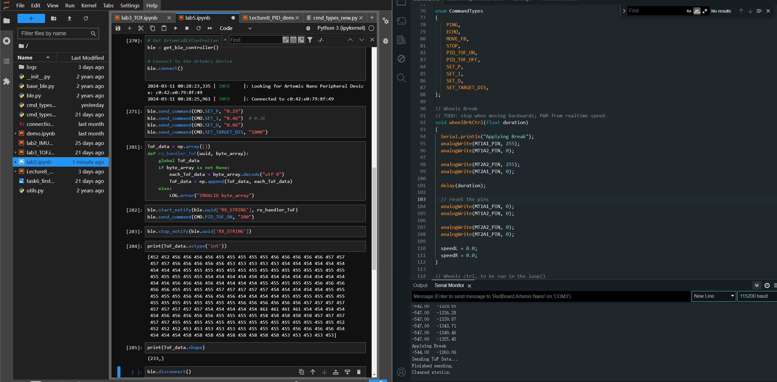
Here is a screen recording showing the whole process (connecting the car via BLE -> set parameters & enable notification handler -> trigger PID controller & record ToF data -> PID controller self-shutdown after 5sec -> apply break -> send collected data via BLE -> check out received data & disable notification handler). The car is connected to PC via serial for displaying debugging status.
Task 1: P/I/D Discussion
As a feedback controller, the Proportional-Integral-Derivative controller (PID controller) takes the error between desired control goal and the actual status as the input. The math expression
is listed below.
\(
u(t) = K_p e(t) + K_i \int_{0}^t e(\tau) d\tau + K_d \frac{d e(t)}{d t}
\)
This mermaid flowchart may help explain the data stream of a PID controller:
\( K_p \): Proportional parameter, to be multiplied with the residual between actual state and the desired setpoint. Increasing \( K_p \) helps accelerate the convergence speed, but with risk of adding overshoot.
\( K_i \): Integrational parameter, to be multiplied with the integration (accumulated error over the timeline) of error. An appropriate value of \( K_i \) helps maintain the accuracy to the setpoint when the system converges. An excessively large \( K_i \) will introduce fluctuations to the system.
\( K_d \): Derivational parameter, to be multiplied with the derivation (or the residual between consecutive errors in the timeline) of error. Increasing \( K_d \) strengthens the system's stability and responsing speed to sudden changes to the state. An appropriate value of \( K_d \) helps suppress the overshoot of the system.
Task 2: Range / Sample Time Discussion
Range Discussion: we use the Sparkfun head file to instantiate the distance sensors, so there are 2 modes to choose. The long range mode has a max range at ~4m, the short range mode
has a max range at ~1.3m. So here we choose the long range mode for the sensor mounted at the front of the car.
Sample Time Discussion: the loop speed may be faster than the ToF sampling rate (~10Hz), so Interpolation is needed for predicting the current error to be fed into the PID controller.
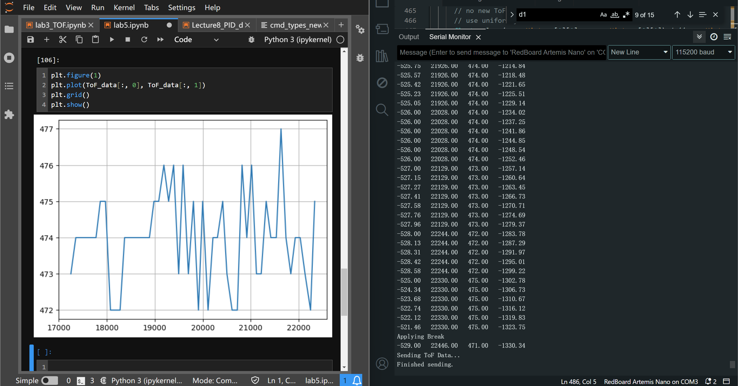
In the following screenshot, the robot is placed still, measuring a fixed distance. In the serial monitor on the right hand side, the printed data are (from left to right):
calculated (including interpolated) error, current time stamp of the ToF data, current reading of the ToF sensor, the output PWM for the motors(ignore this).
During 5 seconds, there are 57 data points from the ToF sensor collected (11.4Hz), the main loop will call the PID controller 5~7 times during the inverval of ToF time stamp updates.
Thus we can conclude that, after implementing all the main features of the program, the main loop runs 5~7 times faster than the ToF update rate. The interpolation algorithm will be in use during such period
where no ToF data is updated.
Task 3: Demos of Reaching Task Goal
The code implementation of the PID controller is shown below:
// INPUT: interval vals, including dt and error;
// OUTPUT: change the global of speedL and speedR.
void PID_FB(){
static float lastTime = millis();
static float lastToF = 0.0; // to compare if the tof is new. If not, use interpolation.
static bool extrapolateReady = false;
static unsigned int idxPointer = 0;
// ---- PID parameters ----
float error = 0.0; // the residue between desired and actual measure
static float errorI = 0.0; // the accumulated error (integration of error over dt)
float errorD = 0.0;
float errorP = 0.0;
static float errorExtra = 0.0; // the previous extrapolated distance.
// ---- acquire the time interval between two loops
float dt = (millis() - lastTime) / 1050;
lastTime = millis();
// ---- control the duration ----
static float startTime = 0.0;
if(PID_TOF_IS_ON){
// ---- calculate error, update eror history.
// extrapolate when at least 2 tofs are acquired.
// try to fetch ToF
if(d1[0] != lastToF){
error = d1[1] - desired_distance;
lastToF = d1[0]; // update the record.
errorHistory[0][0] = errorHistory[1][0]; // shift stamp
errorHistory[0][1] = errorHistory[1][1]; // shift error readings.
errorHistory[1][0] = d1[0]; // update the stamp (pop in)
errorHistory[1][1] = error; // update the reading (pop in)
if(errorHistory[0][0] != 0.0 && extrapolateReady == false){
// acquired 2 tof data, extrapolation is ready.
extrapolateReady = true;
}
errorExtra = error;
// decide whether to stop and send via BLE
if(startTime == 0.0){
startTime = millis();
}
static unsigned int idxStorage = 0;
if(millis() - startTime <= maxDuration && idxStorage < maxToFAmount){
itoa(int(d1[1]), tofStorage[idxStorage], 10); // int to char
itoa(int(d1[0]), tofStamps[idxStorage], 10); // store the stamps
idxStorage += 1;
}
else{
actualAmount = idxStorage; // pass to global
idxStorage = 0; // reset
PID_TOF_IS_ON = false; // turn off PID
startSend = true; // in main loop
startTime = 0.0;
}
}
else if(extrapolateReady = true && d1[0] == lastToF){
// no new ToF, use extrapolation
// use uniformly accelerated motion model.
float vel = (errorHistory[1][1] - errorHistory[0][1]) / ((errorHistory[1][0] - errorHistory[0][0]) / 1000);
float acc = vel / ((errorHistory[1][0] - errorHistory[0][0]) / 1000);
errorExtra = errorExtra + 0.5 * acc * sq(dt) + vel * dt;
// errorExtra = errorExtra + vel * dt;
error = errorExtra;
}
// ---- pop the consistent error history ----
errorHistoryConsistent[0] = errorHistoryConsistent[1];
errorHistoryConsistent[1] = error;
Serial.print(error);
Serial.print(" ");
// Serial.print(d1[0]);
// Serial.print(" ");
// Serial.print(millis());
// Serial.print(lastToF);
// Serial.print(" ");
Serial.print(d1[1]);
Serial.print(" ");
// ---- implement PID speed update----
if(lastToF != 0.0){ // when we have at least one ToF reading.
// calculate the d-error and i-error
errorD = errorHistoryConsistent[1] - errorHistoryConsistent[1];
errorI = errorI + error * dt;
// implement PID filter
speedFB = Kp * error + Ki * errorI + Kd * errorD; // distance is in mm unit。
Serial.println(speedFB);
if(speedFB > maxPWM){ // max pwm will be 255 / caliFactor
speedFB = maxPWM;
}
else if(speedFB < -maxPWM){
speedFB = -maxPWM;
}
else if(speedFB >= -93 && speedFB < 0){
speedFB = -93;
}
else if(speedFB <= 93 && speedFB > 0){
speedFB = 93;
}
speedL = speedFB;
speedR = speedFB;
}
}
else if(extrapolateReady == true){
// clear the statics, only once.
// errorHistory and errorHistoryConsistent has been cleared in the handle_command() function.
wheelBrkCtrl(100);
extrapolateReady = false;
idxPointer = 0;
errorI = 0.0;
errorExtra = 0.0;
lastToF = 0.0;
speedFB = 0.0;
speedL = 0.0;
speedR = 0.0;
errorHistory[0][0] = 0.0;
errorHistory[0][1] = 0.0;
errorHistory[1][0] = 0.0;
errorHistory[1][1] = 0.0;
errorHistoryConsistent[0] = 0.0;
errorHistoryConsistent[1] = 0.0;
Serial.println("Cleared statics.");
}
}
Initially, we use conservative settings for exploring an approximate range of the parameters. The desired distance to the wall is set to \( 304 \)mm (i.e. length of one tile).
The deadband of the motors are set to \( [93, 180] \), since the minimum duty to overcome static friction is 93/255, and the maximum duty before multiplying by the calibration factor
is 180/255. During each run, the time stamps and corresponding ToF readings are recorded and they will be sent over BLE after 5s.
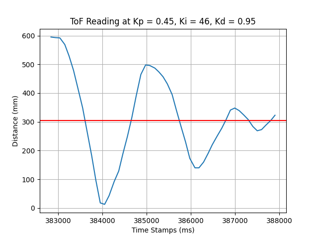
At 71cm, start the car at max speed (duty = \( \frac{180}{255} \)), with \( K_p = 0.45, K_i = 0.46, K_d = 0.95 \), the car crushes into the wall. Refer to the diagram below.
Increasing \( K_p, K_d \), we can see the car is able to stop before crushing into the wall, but it converges inaccurately.
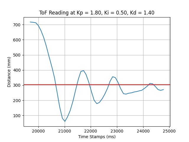
Adjusting \( K_p, K_i \), the car converges to the proximity of 304mm, and stops at the 5th second running the PID controller. In this case, the system still converges slowly and the undershoot is larger than the overshoot.
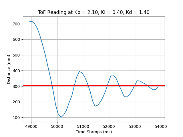
If we increase \( K_d \) to 1.60, \( K_p \) to 2.20, the system convergence speed will be largely improved. But the system undershoot appears more obvious than before. Consider increasing \( K_i \) and fine-tuning \( K_d, K_p \).
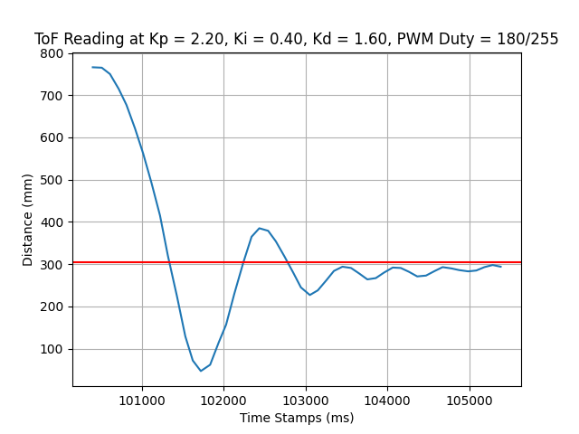
At this parameter setting, the behavior of the car can be seen below. The function to apply break should be adapted to cater to different speeds.
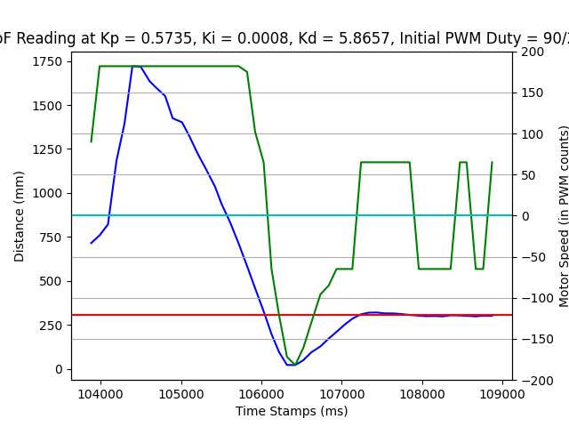
Viable parameter setting: After tuning for a while, the car starts at ~2000mm and stops at 304mm at \( K_p = 0.5735, K_i = 0.0006, K_d = 5.8657 \), see the video below.
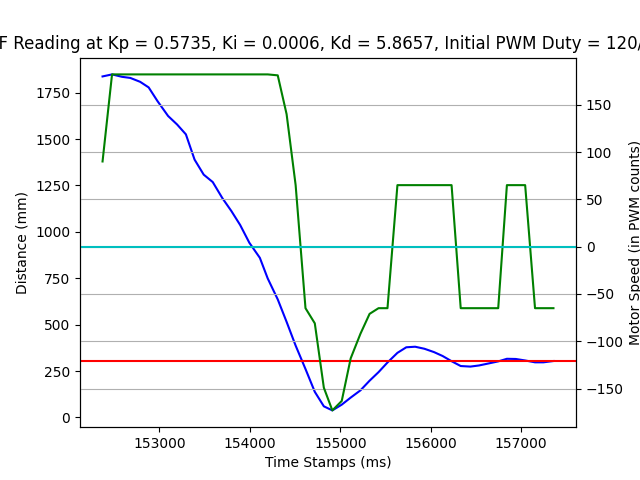
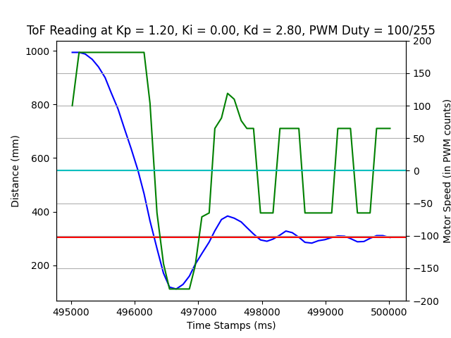
There are also other params that work, see the log images below.
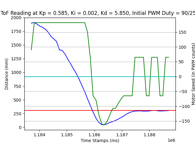
Note: PD Controller: if we use PD controller, it also works.
Additional Task: Wind-up Implementation and Discussion
Wind-up in the PID controller refers to the phenomenon when the integration error accumulates over time, it dominates over the all 3 error inputs and causes slow response and fluctuations to the system. When the car approaches to the setpoint, the control output should slowly decrease (the motor speed should slowly decrease). But a large integrational term will make the sum of P/I/D terms still very large, the decreasing rate of P/D terms is subtle compared with the increasing rate of the I term. Thus the motor will actually speed up instead of slowing down.
                                        float maxErrorI = 150.0;  // in mms.
                                        float cutoffErrorI(float ErrorI){
                                            if(ErrorI > maxErrorI){
                                                ErrorI = maxErrorI;
                                            }
                                            return ErrorI;
                                        }
THE END