1 Objectives
The goal is to gain basic experience on the software IDE and the connection of the Artemis Nano board. Also, several demo codes will be tested where we can learn the manipulation of fundamental peripherals.
2 Prelab
Before we connect the board with the computer, we have to install Arduino IDE and get relative board definition files ready. For reference for later students, the lab is done with Windows 11.
The Arduino IDE can be downloaded here within seconds. After finishing installation, we can click Tools -> Board -> Board Manager to select the board we need. There will be pre-installed the Arduino AVR series. If your are familiar with STM32 + Keil5, then you can compare the board manager with the menu in Keil where you install board description files. With the board description file, one can used predefined variables or functions which are already hard linked to the pins and registers of the MCU.
Thus, we have to add new boards into the IDE, follow this page to add the Artemis Apollo board series description file into the Arduino IDE.
3 Connecting
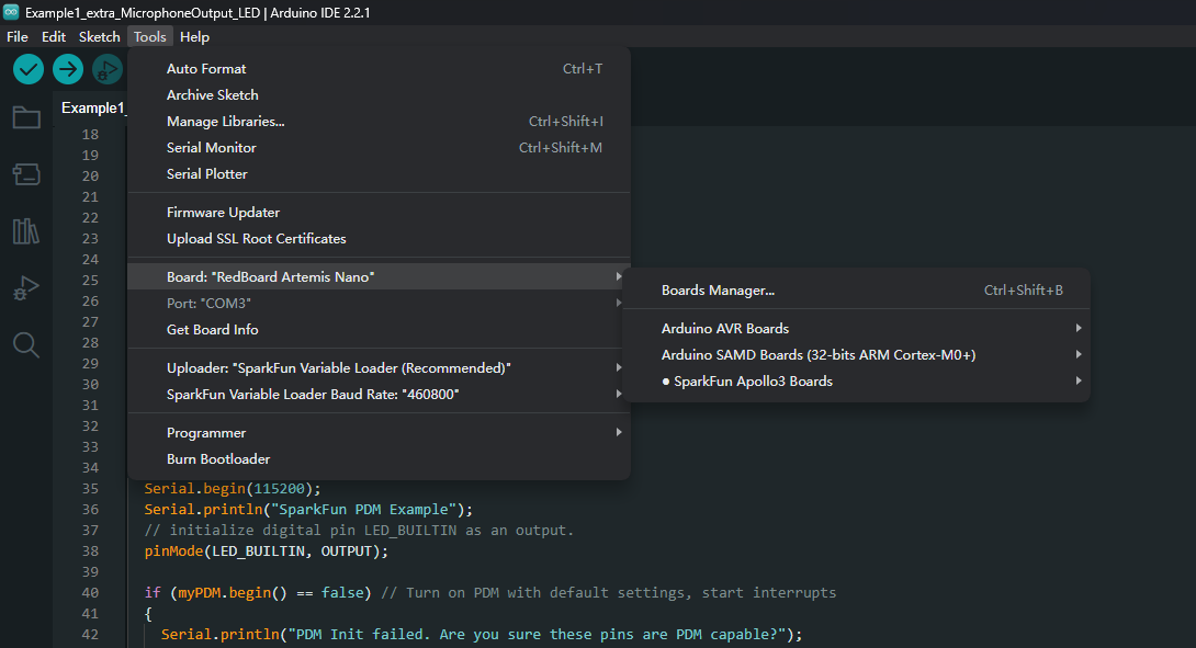
Now we have finished preparing the IDE, connect the board with PC. Through the Device Manager on the PC, we can see one new serial device connected to port COM3 (usual cases). After that, we still have to select the board in the IDE to make sure the IDE recognizes the board. Refer to the image below.

We can open the serial monitor to check if the board is correctly connected. Make sure the Baud rate is set to 115200Hz, type in the box and the board will echo back the message you sent.
4 Demo: Blinking
There's an example code in "File -> Examples -> 01 Basics -> Blink". Open the project (called "sketch" in Arduino IDE) and save as another local file. Upload it onto the board, we can observe the blue LED below the "RX" LED blinking at a constant interval (default set to 1000ms on and 1000ms off).
5 Demo: Serial Communication
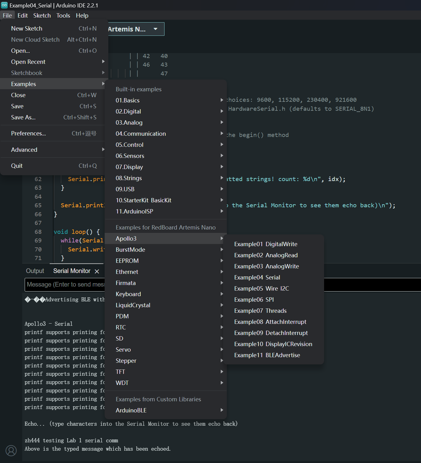
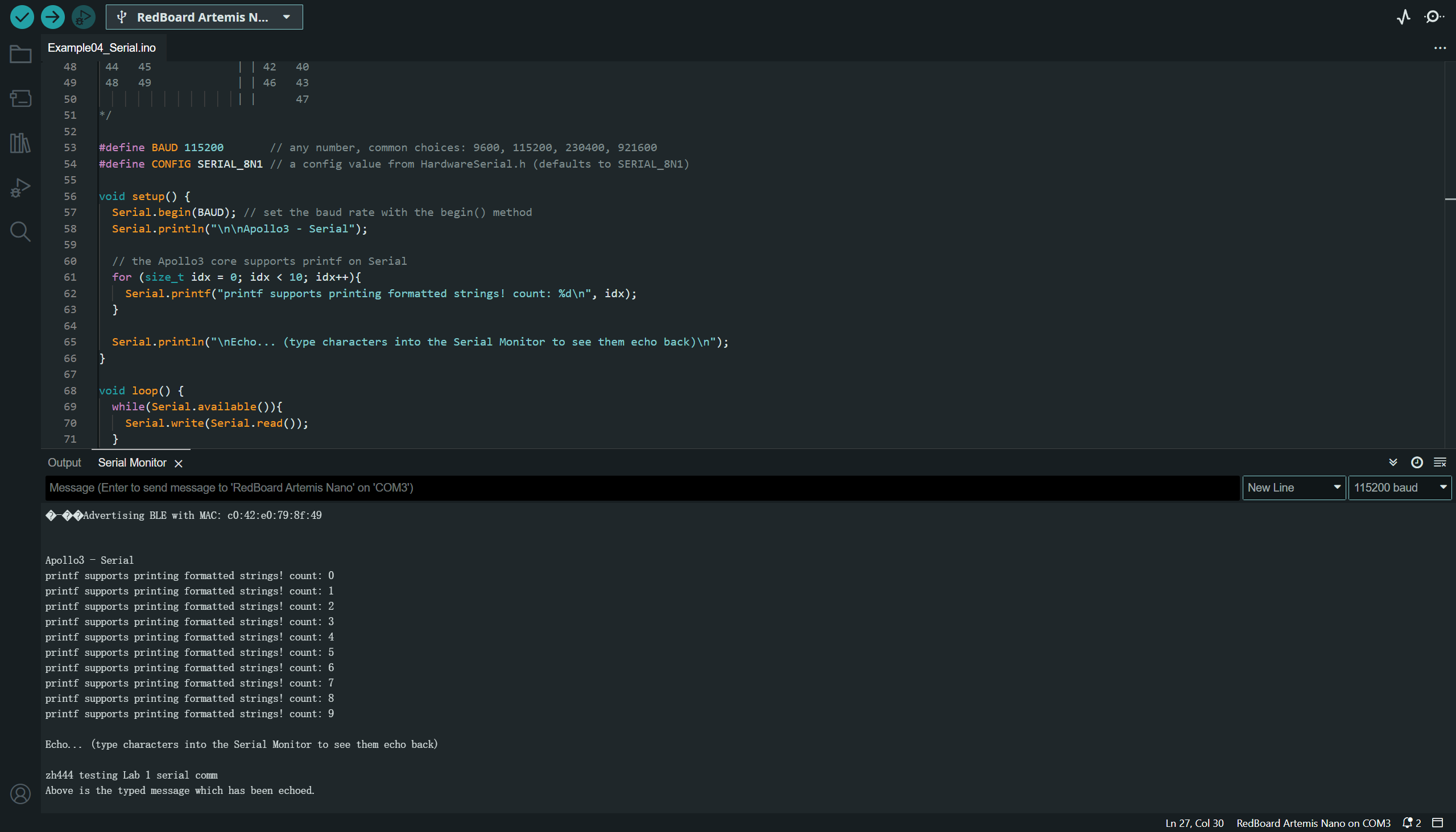
Upload the serial communication demo code in "File -> Examples -> Apollo3 -> Example04 Serial". Open the Serial Monitor and type in the box (with 115200Hz Baud rate). The same text will be returned and displayed in the terminal. Refer to the image below.

The result is shown below.

6 Demo: Analog Reading
Upload the temperature reading demo code in "File -> Examples -> Apollo3 -> Example02 AnalogRead". This section uses the temperature sensor on-board as the data source, the readings will be returned to the Serial Manager. It will return a group of data each time, including the analog voltage on the external ADC pin, the VCC across the 1/3 voltage divider, the reference VSS, the raw ADC counts from die temp sensor, the computed temp in F degrees and the computed supply voltage in V.
The result is shown in the video below. I held the whole board in hand, and released it after a while. The temperature climed slowly from 33F to 35F, and dropped at a faster speed to 33F after I released the board.
7 Demo: Microphone Output
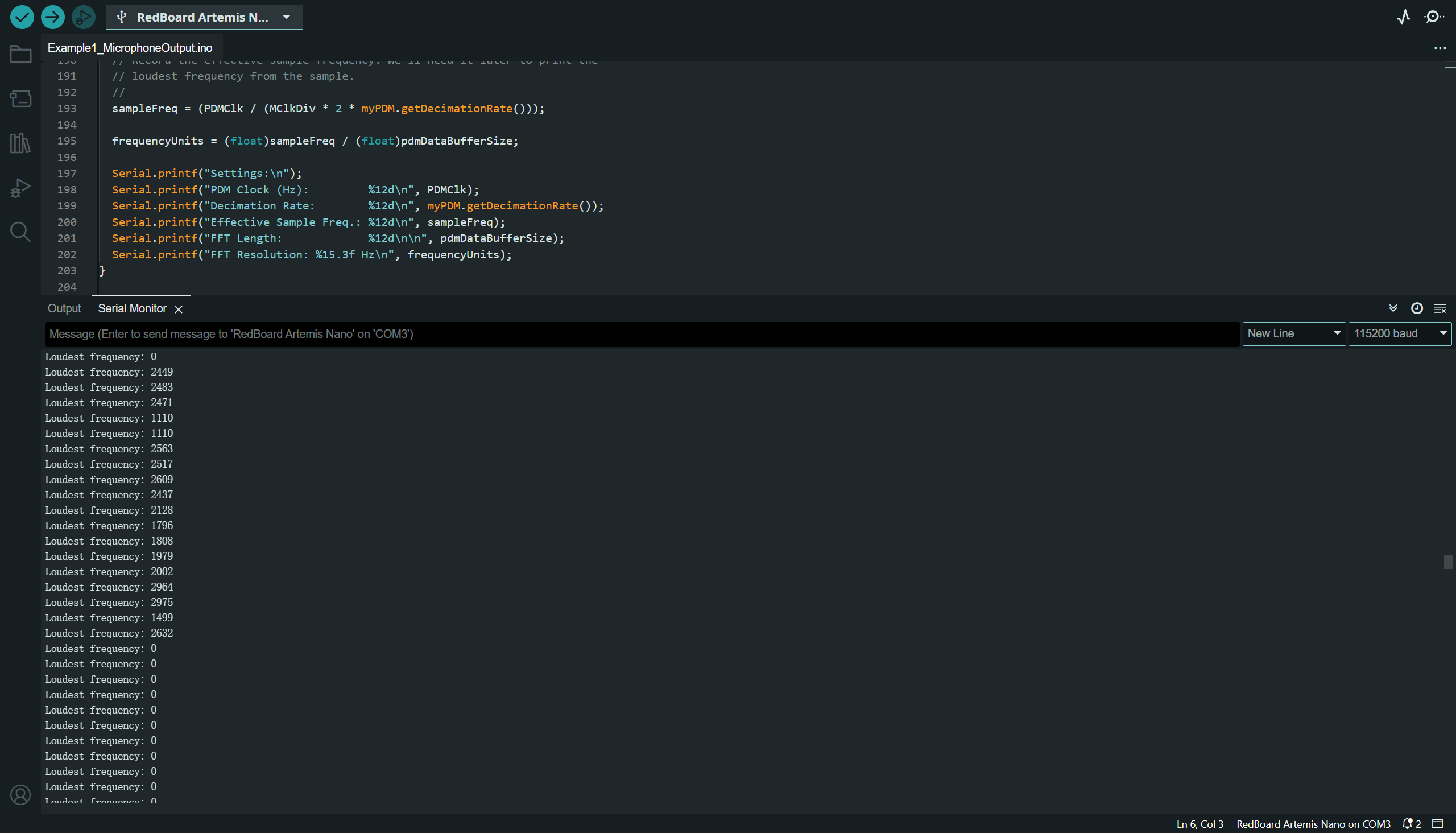
Upload the temperature reading demo code in "File -> Examples -> PDM -> Example1 MicrophoneOutput". The board will return the calculated effective sample sound frequency in the Serial Monitor.

8 Additional Task: Pitch Triggered LED
In this section, I used the web piano to generate a standard musical A key (the tone "la", measured as 881Hz). When there is a A tone being generated, the blue LED will be activated. The result is shown in the video below.
THE END