IROS 2025 Oral: We will be giving our IROS 2025 oral presentation on Thursday, Oct. 23, and we will hand out homemade original 3D printed souvenirs at the poster session afterwards (limited amount!).
Location: Room 103B, Hangzhou International EXPO Center, Hangzhou, China
Time Slot: 3:00PM-3:40PM, Thursday, Oct. 23, 2025
Oral Speaker: Zhongming Huang (contact him)
We recommend that you view this page in landscape mode on your phone or on a PC.
Robust Robotic Assembly of Reusable Rectangular Blocks
Zhongming Huang, Hongyu Yao, Haocheng Peng, Shih-ming Lin
Advised by: Prof. Kirstin Petersen and Prof. Nils Napp*
Department of Electrical and Computer Engineering
Cornell University
Before you read: this page is built for everyone to grab a general idea of our work. If you would like to dive deeper, please refer to our paper. This page also contains extra background information not selected in our paper.
Robust Robotic Assembly of Reusable Rectangular BlocksTable of ContentsOverviewGeneral Introduction of Robotic ConstructionCollective Robotic Construction (CRC) and TERMES SystemOur WorkOur ContributionOff-the-shelf and Reusable Materials and FastenersSpecialized Grasp and Nailing MechanismImproved Local Rule Set and CompilerPerception and ControlBuilding an L-shaped StaircaseFuture WorkBehind the SceneBlock DispenserReal-time Visualizer
Overview
General Introduction of Robotic Construction
Automated construction has emerged as a key frontier in robotics, prized for its potential to reduce human labor and to operate reliably in challenging or hazardous environments. Over recent years, a diverse set of construction robots has been developed, which can be broadly grouped into the following categories (may not be precise enough, for introduction only):
FDM Printing Robots: similar to desktop-scale FDM printing (some may use gantry systems, others use a robot arm to hold the extruder), a cementitious material is extruded layer by layer, and steel reinforcement may be co-fabricated in situ.
most existing commercial applications.
Weaving Robots: they construct a structure by weaving/winding systems build load-bearing 3D lattices without traditional formwork.
Truss Building Robots: they can climb on the truss framework while transporting and fixing more trusses onto the existing structure.
Block Placing Robots: they stack building blocks (e.g. foam bricks) similar to their body size, to form a structure.
Our robot.
Self-reconfigurable Modular Robots: they use their bodies as building elements, climbing over one another to form and reconfigure diverse structures.
......
Collective Robotic Construction (CRC) and TERMES System
Most of the previously mentioned systems do not rely on gantry mechanisms. Instead, they transport and attach building elements by locomoting around the site, flying over the structure, or climbing directly on it. Our construction robot falls into the category of climbing robots (see this Science Robotics review for a definition). Also. most of these works consisted of a group of agents to parallelize the construction process. When it comes to multi-robot construction, we would naturally expect the system to be:
scalable (structure size, agent amount);
generalizable (lower demand on specific the building material);
cost-efficient (both material and the agents themselves).
One way to achieve those goals is to draw inspiration from the nature, adopting how insects build large structures exploiting collective intelligence. Many insects only have low-level perception and communication, such as termites (most termites are even blind). Nevertheless, they as a collective can still build structures way larger than their body size. Natural systems like this represents great value in guiding how we design each agent, as well as how they organize and collaborate.
Inspired by the termite's ecosystem, the TERMES system was introduced, where each robot is equipped with simple sensors and actuators, yet together they can assemble structures much larger than themselves by climbing, navigating, and manipulating specialized building blocks. Unlike traditional construction methods that rely on centralized planning or heavy machinery, TERMES embraces collective intelligence: multiple identical robots act independently, following local rules and responding to their immediate environment. This decentralized design makes the system robust, scalable, and cost-effective, capable of operating in challenging environments such as disaster zones or extraterrestrial surfaces.
In simple words, the original TERMES system mainly contributed to:
robot and material co-design (i.e., fabricated specific foam blocks with visual patten and magnets);
structure complier (i.e., how to translate the target 3D structure into feasible combination of building blocks, and present it as a grid map with traversing directions and target height);
local rules (i.e., how each agent choose the next action, solely based on the directed grid map, and the observation of a very close vicinity, with very frugal perception).
Note: the compiler and local rules are highly correlated. The structure compiler will only be executed once, before construction starts, then the directed grid map will be downloaded to each agent with identical local rules.
Our Work
Multiple papers on the TERMES system have been published in Science, RSS, and RAS. However, one significant limitation remains: generalizability. This challenge can be broken down into several aspects.
First, the system relies on highly specific building materials. While this approach is beneficial for prototyping and concept verification, it is far from practical for real-world deployment. The TERMES system, for instance, employed lab-fabricated foam blocks with visual markers, customized geometries for grasping and climbing, and magnets embedded in the corners for fastening.
Second, the system uses an impractical layer pattern. The blocks are identical squares, each corresponding to a cell in the directed grid map, but they cannot form interlocking patterns across layers. In contrast, real-world masonry follows a staggered, interlocking arrangement, where each brick overlaps two beneath it. The absence of such interlocking leads to "vertical runs," which we have tested in simulation to be structurally weaker in earthquake-like stress tests. Interlocking, by comparison, provides far greater resilience.
To address these limitations, our system aims to:
adopt off-the-shelf and reusable materials and fasteners,
design local rules that guarantee interlocking features wherever feasible,
and develop a compiler that actively minimizes vertical runs.
Our Contribution
Note: in this section, we only introduce ideas and mechanisms. For detailed tests and proofs, please refer to our paper.

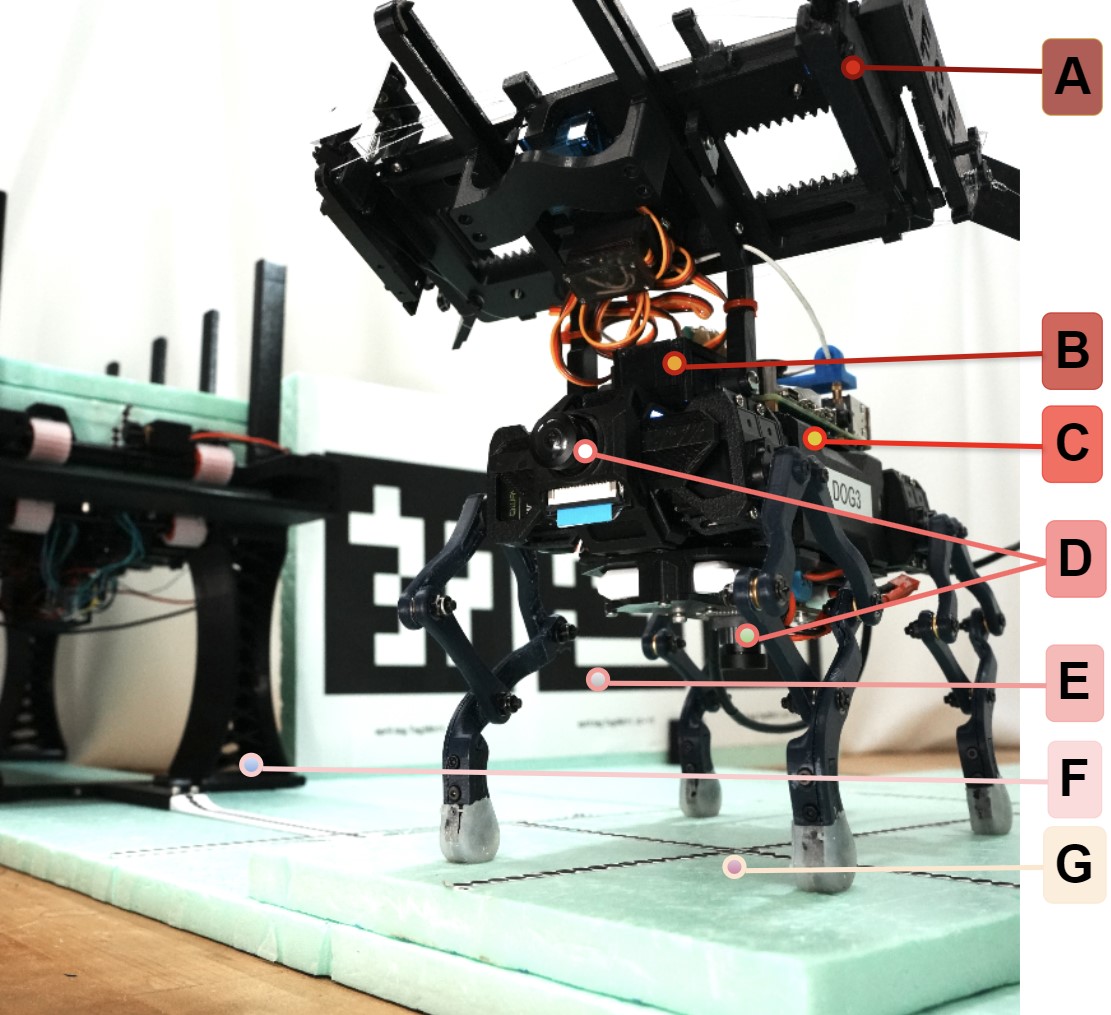
The figures above shows our core contributions:
a compiler that actively minimizes vertical runs, and compiles the target structure into a directed grid map;
a local rule running on the robot to decide its route and whether to place a 2 by 1 block at each grid, it allows parallel construction that eventually results in Figure 1;
minimally processed materials (Figure 2-G);
specialized grasp and nailing mechanism (Figure 2-A);
perception and gait control with visual feedback (Figure 2-D);
Other contributions not selected in our paper will be briefed in Section "Behind the Scene".
Off-the-shelf and Reusable Materials and Fasteners
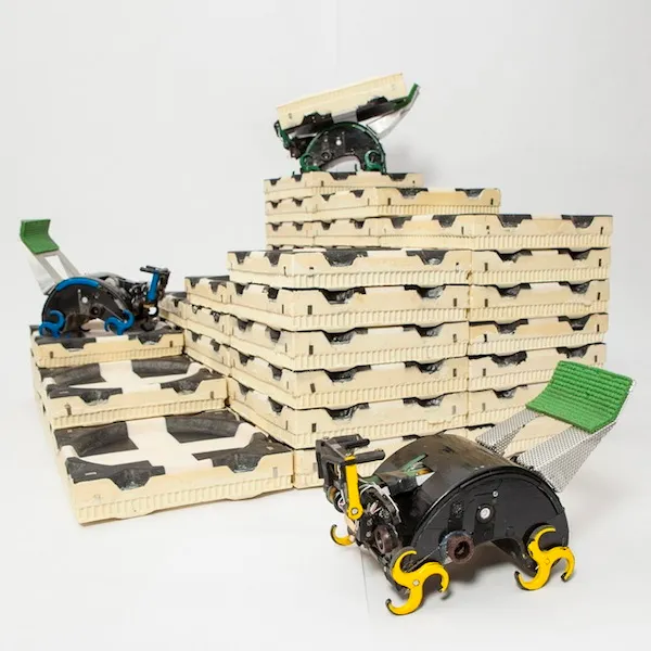
Instead of spending hours to mold the specifically designed blocks that TERMES uses, we cut Kingspan insulation foam boards into
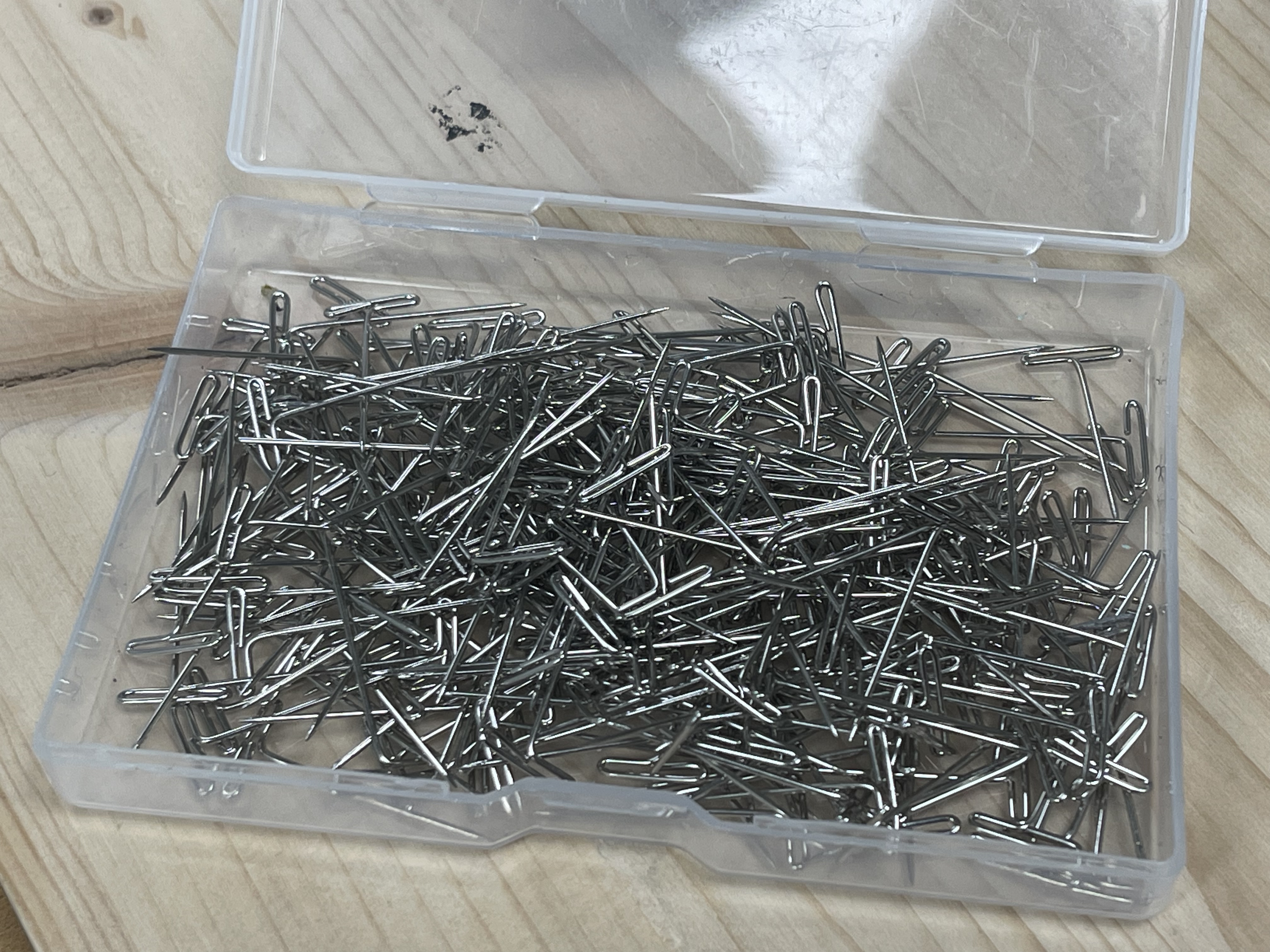
In accordance with the minimally processed blocks, we choose T-pins (T-shaped steel staples) to fasten the blocks. Each T-pin is able to penetrate into two layers of blocks, providing
Specialized Grasp and Nailing Mechanism
The co-design of materials and robot is a balancing trade-off. With our building materials easy to get, our robots should be more specialized in manipulation with those materials, which is more generalizable for future applications. Specifically, we designed:
a gripper to grasp, carry and place the blocks;
a pair of nailing mechanisms to store and fix the T-pins.
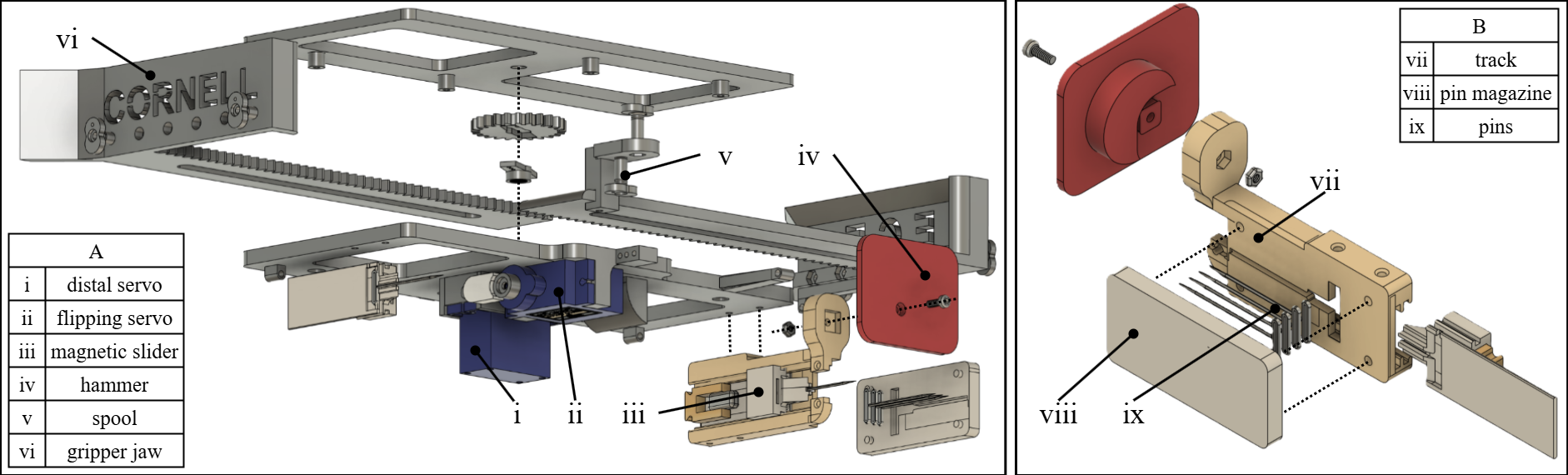
The gripper is controlled by two MG-90 servo motors, as shown in parts (i) and (ii) of subfigure A:
the flipping servo controls the rotation of the whole gripper. When placing the block, (ii) will drive the gripper to rotate for
the distal servo controls the opening and closing of the jaws (vi) of the gripper, as well as the reload and push-out of the T-pins (which will be highlighted next). When fetching a new block from the dispenser, the jaws simply opens and closes to hold the block very tightly.
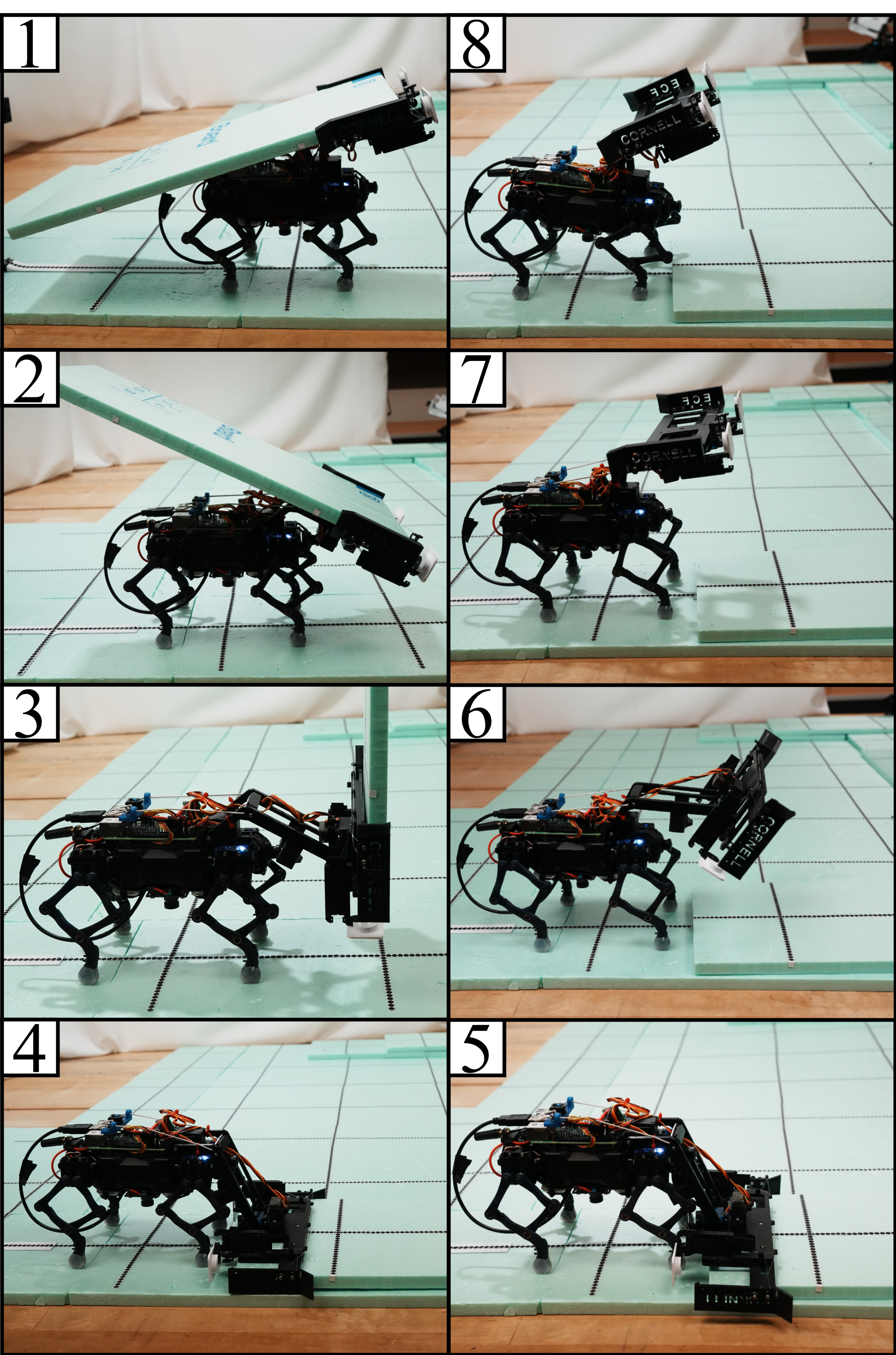
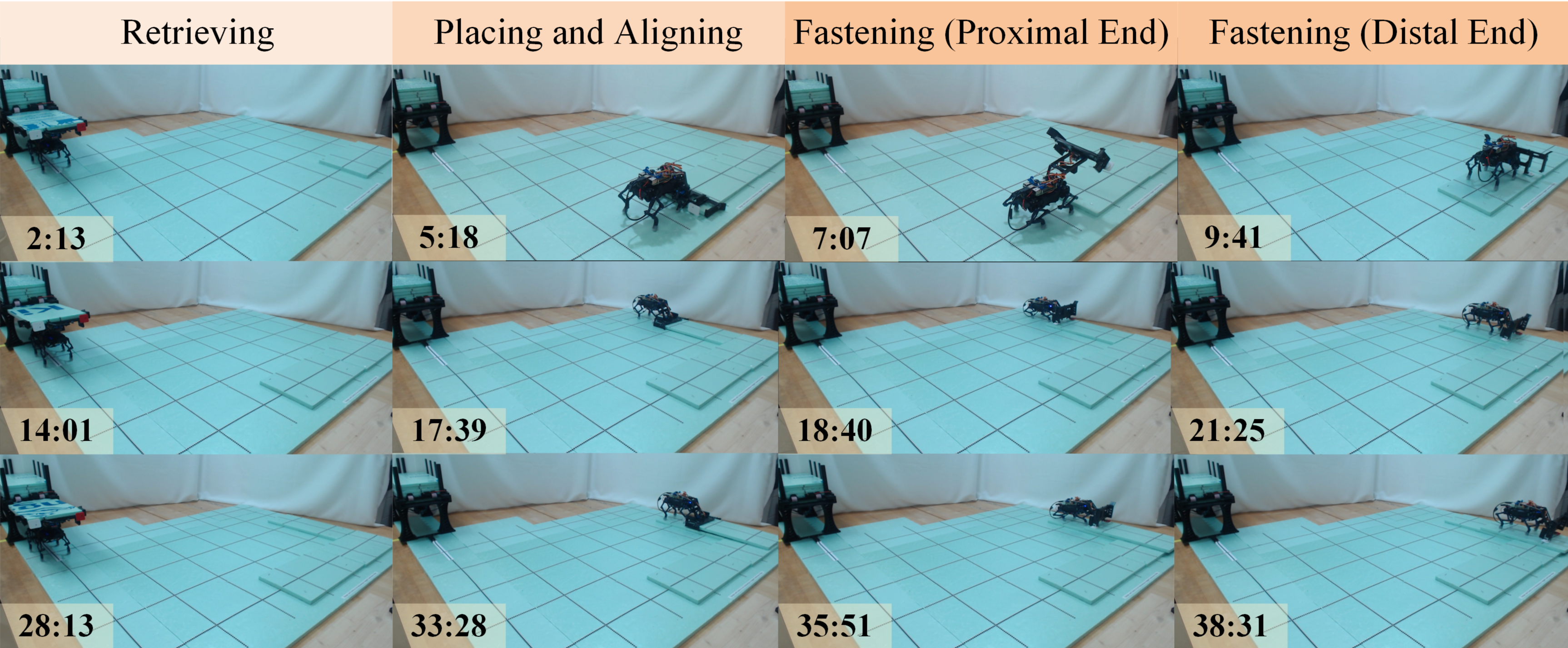
The figure above demonstrates the whole process of placing and aligning a new block (nailing T-pins is not included here and will be shown next). From 1 to 8:
The robot arrives at a grid and decides to place a 2 by 1 rectangular block.
The robot lowers the linkage and prepares to rotate the gripper.
Note: the pair of linkages incorporate a sliding rail inside, enabling the gripper to fall to its lower end under the effect of gravity and inertia.
The block is rotated to vertical position, and the gripper will temporarily slightly open to eliminate the gap between the block and the bottom end of the gripper, under the effect of gravity.
The gripper rotates, and the block touches the ground, the robot will align this block with the existing structure.
Alignment finished, the gripper jaw opens to release the block.
The linkages lift up the gripper and the robot prepares for nailing.
The gripper rotates to the initial pose.
The gripper can slide back to the proximal end of the linkages while walking.
The nailing mechanism only has one degree of freedom, and we connect the magnetic sliders (iii) with the spools (v) on each jaw with fishing wires. In this way, when the jaws open, the slider can be pulled back and one T-pin on each side can be attracted to the slider. When the jaws close, the T-pin on each side can be pushed out and ready to be nailed.
Note:
We precisely adjusted the tightness of the spools and the dimensions of the track and magazine (vii, viii) to ensure:
the grasp and placement of a block will not unexpectedly push out a T-pin;
for each side, only one T-pin can be pushed out a a time;
T-pins do not get stuck in the track.
This part requires intensive engineering efforts.
The following video shows how the robot nails two T-pins at the corners of a block at one time. When the process is finished, the robot will swing its linkages and smash the T-pins with the hammers (iv), to drive them into the next layer of blocks.
Video 2. Placing Two T-pins at a Time
Video 3. Placing and Securing Two T-Pins for the Next Layer
Improved Local Rule Set and Compiler
Our system introduces an improved compiler that automatically optimizes the placement of overlapping rectangular blocks in user-specified structures. Instead of relying on manually defined entry and exit sub-structures, the compiler uses a constraint satisfaction solver to generate and rank all possible tiling solutions, favoring those with shorter seams and stronger interlocking patterns. This approach not only reduces tedious human intervention but also greatly improves stability, as shown in simulation tests where optimized overlaps allowed towers to withstand significantly greater disturbance before collapse.
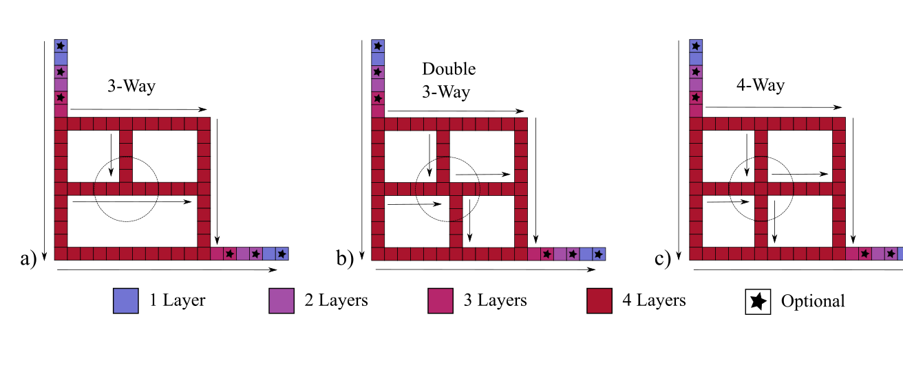

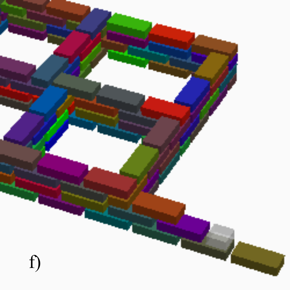
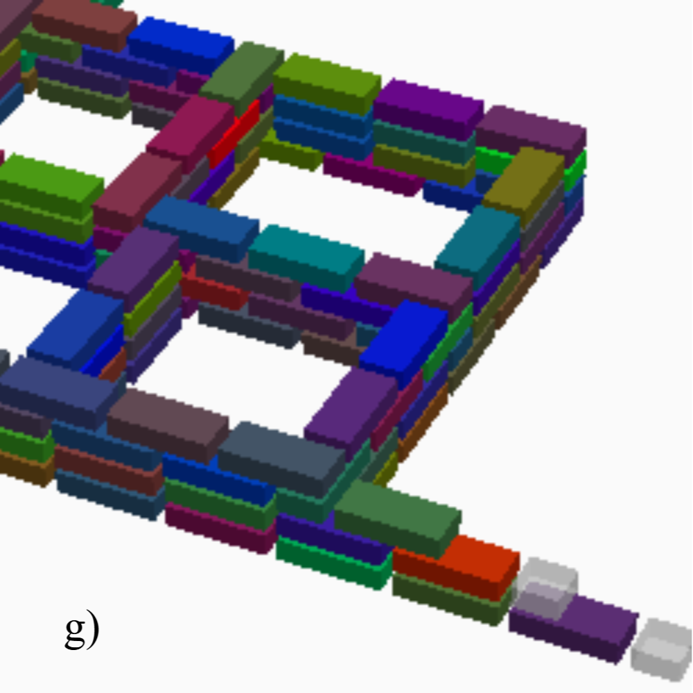
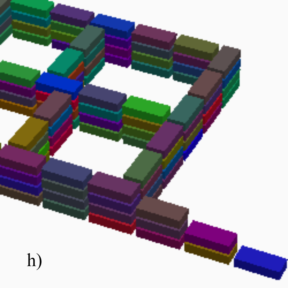
In the above figures: a–c) Top views of test structures with travel directions and location heights, where circled intersections differ and starred cells mark optional occupancy for compiler optimization; d) side view shows preferred interlocking; e) examples of vertically aligned runs, from 2-layer on the left to 3-layer on the right caused by single gray blocks; f–h) alternative block placement solutions for the double 3-way structure ranked lexicographically by run length and number: best (00.00.37) with no 4- or 3-layer runs and 37 2-layer runs, median (06.17.10) with 6/17/10 runs, and worst (33.02.02) with 33/2/2 runs.
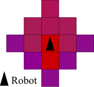
At the same time, we extend the local rule set that governs distributed construction. Each robot relies solely on its local perception, now extended to three grid cells away, to determine whether the block can be placed at the current location. These rules ensure that robots always build on a stable foundation, avoid conflicts through simple traffic policies, and collectively complete user-defined structures without centralized coordination. Together, the compiler and the local rule set enable scalable, robust, and fully decentralized robotic construction, where multiple robots can collaborate in parallel to assemble large, stable structures with minimal overhead.
Perception and Control
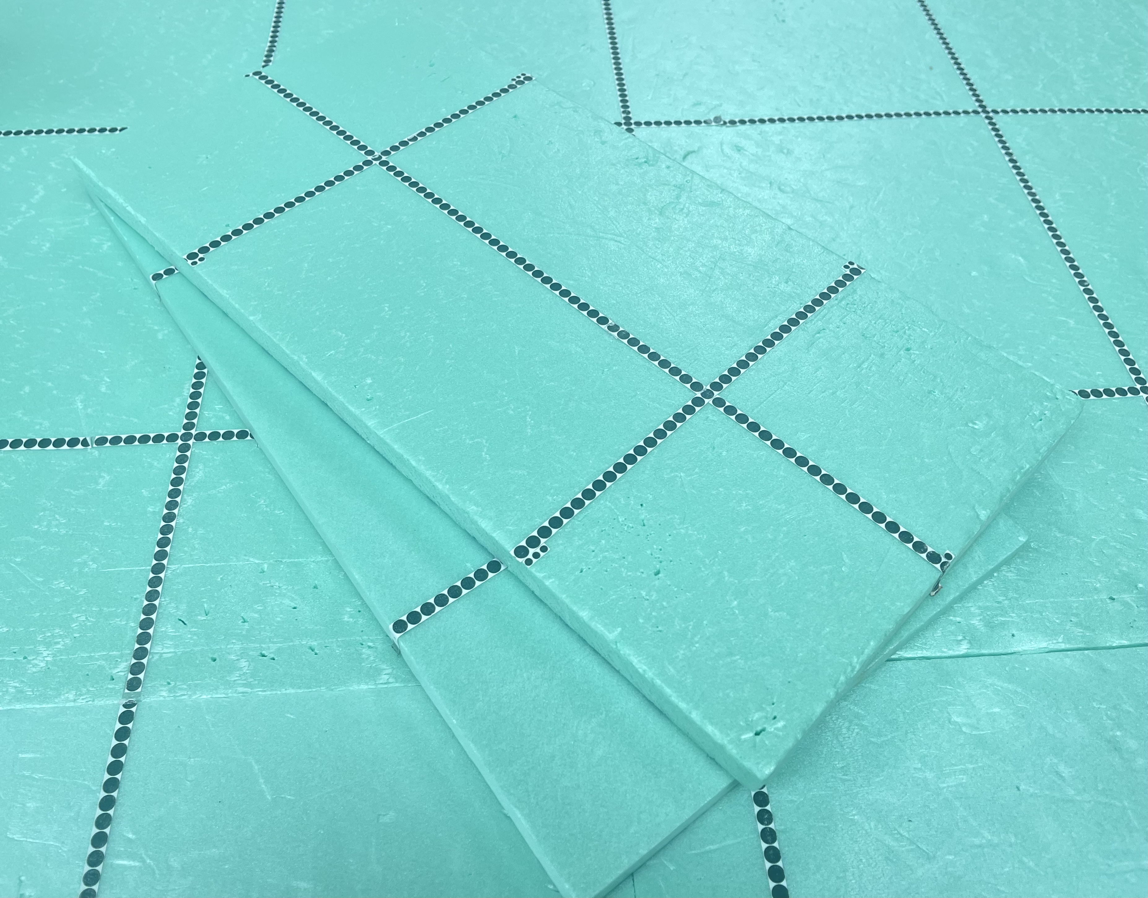
Our robot obtains its yaw from the dotted lines on the floor and adjusts its gait to follow its path, as well as climb and turn.
The following videos demonstrate how we extract the yaw angle from the detection of dotted circles. Our experiments show that the dotted-line pattern is significantly more reliable than other visual markers such as AprilTags, straight lines, or chessboard patterns, especially when frames are seriously blurred during robot locomotion. The relative yaw is calculated from the gradient between neighboring circle centers, meaning that a valid yaw reading can be obtained whenever at least two circles are detected, with accuracy improving as more circles are identified. In addition, the robot detects intersections of orthogonal dotted lines, where each cross corresponds to a grid cell in the directed grid map, allowing synchronization between the robot’s physical position and its logical location in the map. Finally, by carefully tuning both the circle size and the camera resolution, the system achieves yaw estimation at up to 60 fps with less than
Video 5. Dotted Line Detection during Highly Dynamic Locomotion
Video 6. Yaw Extraction from the Dotted Line Patterns
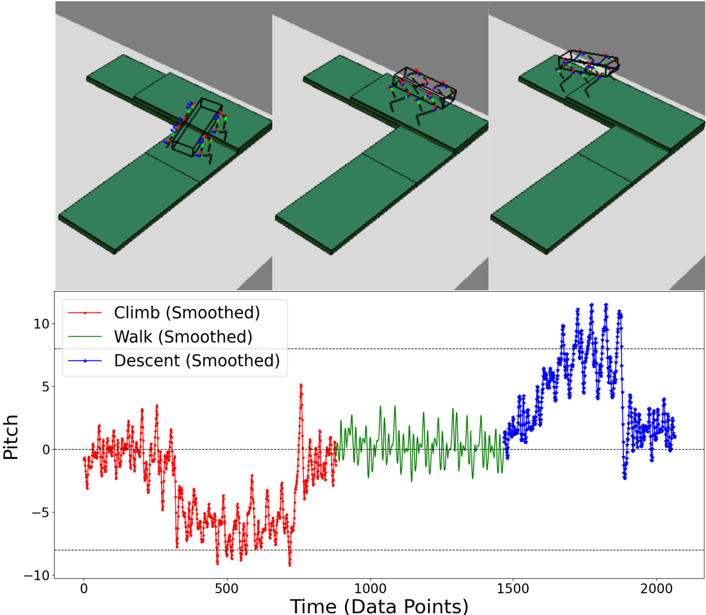
A central challenge in designing climbing and load-bearing quadruped robots is ensuring that the gait remains stable while respecting the torque limitations of small servo motors. Each leg of our robot has three servos, and the front and back joints are particularly sensitive to gravitational load amplification. To quantify this effect, we analyzed the torque amplification ratio (TAR) across the leg’s workspace. When TAR = 1, the servos quickly overheat under load; our experiments showed that the servos can operate reliably at TAR ≤ 0.85. This constraint guided the design of the gait, ensuring that the foot trajectories always stay within a safe operating region.
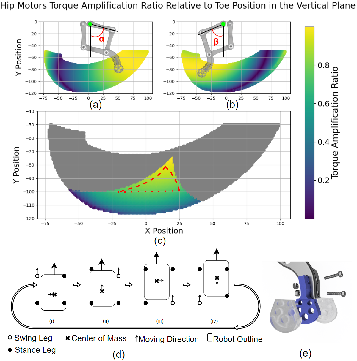
Initially, the commercial platform shipped with a pre-configured trot gait, where diagonal legs move in pairs. While efficient for fast locomotion, this gait is not well suited for carrying heavy payloads or maintaining balance on narrow structures. We therefore discarded the trot gait in favor of a creep gait. In the creep gait, three legs remain on the ground at all times, forming a stable support triangle. The robot continuously adjusts its center of mass so that it stays within this support polygon, significantly improving stability during climbing and block placement.
To further enhance performance, we redesigned the leg linkages and feet. The original nylon feet caused slippage, especially during on-axis turns. Our new detachable feet are fitted with molded silicone pads, which more than doubled both static and dynamic friction in standardized tests. This improvement greatly reduced drift during turning and allowed the robot to execute precise maneuvers on the structure.
With the new gait control and mechanical modifications, the robot demonstrated reliable mobility under load. Its turning radius was reduced to 58.5 mm, which directly informed the minimum block width of 40 cm used in our system. Overall, the combination of torque-aware gait design, the adoption of a stable creep gait, and high-friction feet enabled the robot to walk, turn, and climb while carrying blocks, providing the foundation for robust autonomous construction.
Building an L-shaped Staircase
The video below demonstrates our prototype robot building an 2-layered L-shaped staircase autonomously. The video is speeded.
Video 7. Demostration Video of Building an L-shaped Two-layered Staircase
Future Work
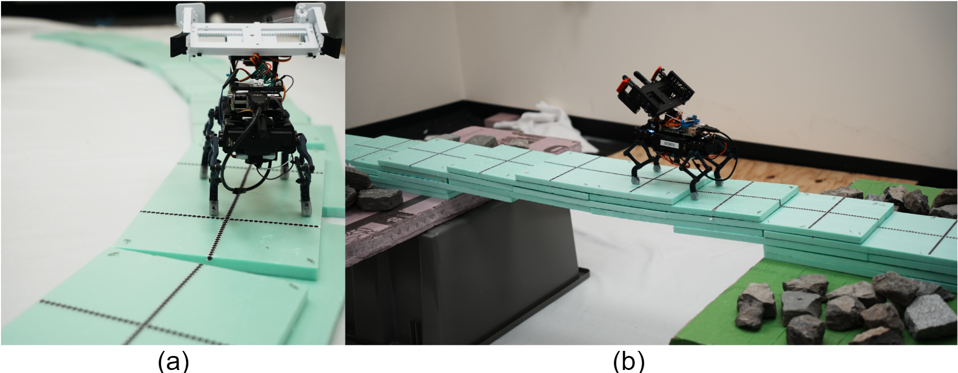
Besides rectilinear walls, we have also established a theoretical guarantee for compiling and constructing curved walls by incorporating tilt angles into the edges of the directed grid map. Our simulations verified that the robots can build curved walls in much the same way as rectilinear ones, with the added capability of tilt angle detection. However, we have not yet resolved how to properly align a new block with an existing curved wall, given the current method our robot uses for block alignment.
Our robot is also capable of locomoting on a corbeled structure, and in theory, we can construct such structures by following a specific placement order (see Fig. 11 of our paper). However, the structural strength of partial assemblies still needs to be improved before the robot can reliably operate on a corbeled arch.
Behind the Scene
Block Dispenser
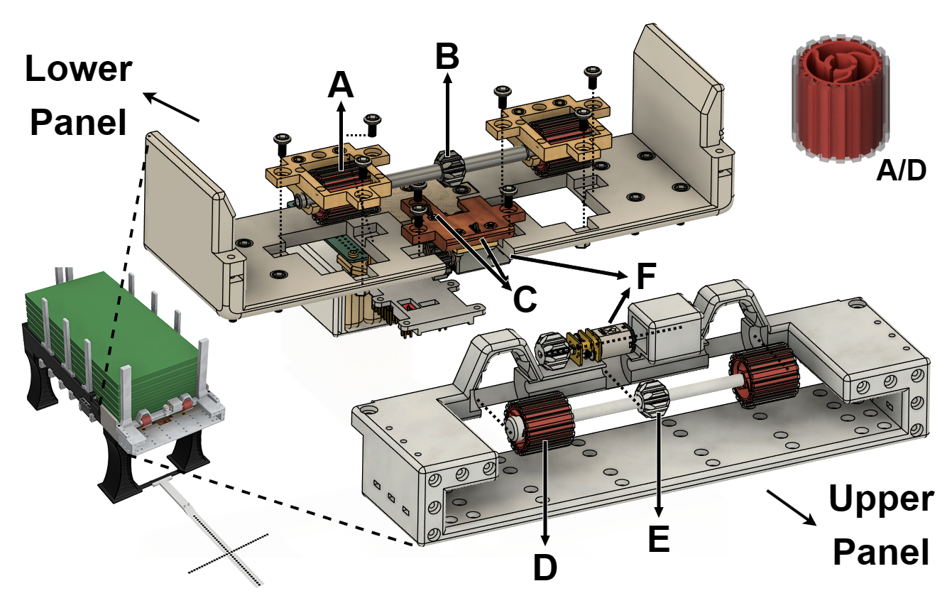
In the demo video, the robot carries one block at a time and retrieves subsequent blocks from the dispenser, which ensures that the entire workflow is fully automated. The dispenser consists of the following components:
A and D: flexible rollers (red part made of TPU, transparent part made of DragonSkin);
B and E: shaft gears driven by separate motors, with rollers fixed to the shaft ends;
C: trigger switches used to detect the position of the bottom block;
F: motors.
For precise localization during block retrieval, the dispenser is rigidly connected to a dotted cross marker.
Real-time Visualizer
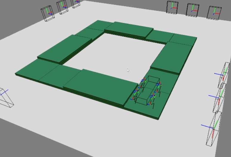
We developed a cross-platform real-time visualizer that receives pose and status information from the robots. Communication between the robots and the PC is established via Wi-Fi using UDP.
As shown in the figures, the visualizer is capable of:
displaying kinematics and inverse kinematics in real time,
providing users with updates on the current structure status as well as the robot’s pose and location.
The system is lightweight and can run smoothly on a Raspberry Pi 4B, which proved especially valuable for debugging.
THE END

Last Updated: Oct. 10, 2025.
© 2025 Zhongming Huang.